Radio Station Tracker
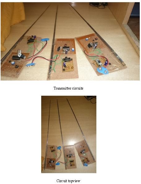
Radio Station Tracker is a project based on Fox hunting which is more common in US and other European countries. It is somewhat similar to our communication system in which if receiver is moving the signal strength would not fade. Basic idea is to transmit a signal using different transmitter with same power so that it would not interfere with other transmitter outside its cell. There transmitter transmits a signal continuously .when receiver is tuned to some particular frequency he would get signal as long as it is under any on the transmitting cell radiation radius or within its cell. The signal which has maximum power will be retrieved by the receiver while other signal will be rejected. This is done with the help of comparison made with the help of microcontroller.
RADIO STATION TRACKER
INTRODUCTION
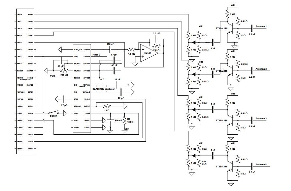
Our project is inspired by the commercial product, PicoDopp, which uses a similar scheme for foxhunting. Foxhunting is contest where participants try to locate a transmitter, called the fox, simply by monitoring the signals it transmits. It is a combination of transmitter and receiver in which receiver is used to locate for the signal which is transmitting from the antenna which is nearest to the receiver. Note that all the transmitters are provided with same power level. In this case what is happening is DTMF is used to send the tone from the transmitter side which is received by the receiver and sent to microcontroller attached to it ,which is decoded by DTMF decoder at the receiver and a analog value is send to the ADC of the microcontroller ,which then is then converted to digital value and which one is nearest to the receiver will be visible in LCD.
APPLICATIONS AND USES :-
- Fox Hunting
- Car Racing
- Tracking without GPS
- For trekking & Mountaineering
FM TRANSMITTER
INTRODUCTION
It is not practicable to send electronic signals over wire to distant places. They are sent by radio. Low frequency signals, as in the audio range, cannot be frequency signals, as in the audio range, cannot be transmitted efficiently, so they are converted to higher frequency called radio frequencies, which can be transmitted effectively over long distance.
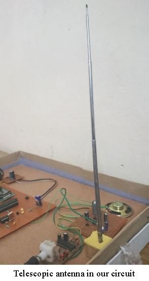
The electronic equipment used to produce radio frequency (RF) signals for radio transmission is called a transmitter. The function of the transmitter is to generate RF carrier of proper frequency and sufficient power. The output of a transmitter is applied to an antenna, which radiates the signal into space. A basic transmitter consists of an oscillator and an RF amplifier. The oscillator generates a continuous sinusoidal output that serves as the carrier frequency. The carrier is amplified to the required power level by the RF amplifier as shown in figure. An antenna connected to the output of RF amplifier radiates the signal into space.
BROADCAST TRANSMITTERS
For interference free reception in a given area, it is necessary that there should be no side band overlapping in the transmitted intelligence. To avoid this over lapping transmitting source that simultaneously cover the same area must use different carrier frequencies.
The following table shows the radio frequency bandwidths covered by the different types of signals and the carrier frequencies at which the signals are commonly transmitted.
According to use, for the transmission of information there are two types of transmitters:
(1) Radio Telegraph Transmitter
(2) Radio Telephone Transmitter (Broadcast)
The difference between the two is that the latter is fitted with modulation equipment whereas in previous, modulation system is replaced by keying system whereby the radiation of energy is periodically turned off and on in accordance with the character of the telegraph code.
FM RECEIVER
INTRODUCTION
FM broadcast in India has gained much popularity and AIR (All India Radio) is now using FM channels for Vividh Bharti programmes also. Although the quality of FM transmission is quite good and stereophonic, several listeners often complain that their receiver, including imported ones, produce quite a bit of noise. Indian market is flooded with such FM receivers which though labeled as stereos, are not really so. Their output power is so low that the stereophonic effect cannot be produced.
AMPLIFICATION
Amplification is the process where by small amount of voltage, current or power at the input side of a circuit is increased so that larger amount of voltage, current or power available at the output side of the circuit. This process is achieved by uses of an active circuit element such as Transistor or vacuum tube or integrated circuit. This circuit is based on the power amplification achieved by Integrated Circuit.
BASCOM AVR & Proteous is used for Coding !!!
Project Developed By-
- YATHARTH SINGH
- SHIVAM ANSHU
- SHUBHAM GAUR
- SACHIN CHAUHAN
If You need more Details about the Project and for Full Report, ppt, Codes etc. Please writes us to yatharth@engineerscorner.in or info@engineerscorner.in


