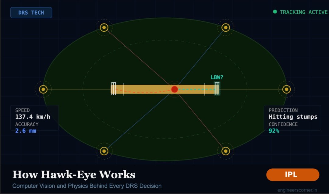
You are watching IPL. A quick delivery hits the pad. The on-field umpire raises the finger. The batting team reviews it. For about two seconds, nothing happens. Then a 3D graphic appears on your screen showing the ball curving through the air, hitting the pad, and continuing toward the stumps in vivid color. Decision overturned. Stadium erupts.
But here is the question nobody really asks: what happened inside that system during those two seconds?
This article breaks down the complete engineering pipeline behind Hawk-Eye, the technology that powers DRS in every IPL match. If you study electronics, computer science, or mechanical engineering, you will recognize the concepts here from your own coursework, only applied at a scale of 140 km/h cricket balls and sold to broadcasters in 20 countries.
What Is Hawk-Eye and Where Did It Come From
Before Hawk-Eye tracked cricket balls, the same underlying technology was used in missile tracking systems and medical brain surgery equipment. The math that helps guide a surgical tool inside the human brain is not that different from the math that tracks a red ball across a cricket pitch.
Dr. Paul Hawkins and David Sherry developed the system at Roke Manor Research in the United Kingdom. It was first used in cricket broadcasting during the 2001 Ashes series between England and Pakistan. At that point it was only for television visuals, not for umpiring decisions.
The Decision Review System (DRS) came much later, in 2008, and Hawk-Eye became its core component for ball-tracking. Sony acquired Hawk-Eye Innovations after that, and today the system is used in more than 20 sports including tennis, football, rugby, badminton, and baseball. The advertised accuracy is 2.6 mm, roughly the thickness of two stacked one-rupee coins.
Step 1: The Camera Setup
Six high-speed cameras are placed on the underside of the stadium roof, spaced 60 degrees apart from each other, forming a full circle around the playing area. These are not regular broadcast cameras. They are JAI monochrome cameras operating at a frame rate of around 120 frames per second.
Two things here are worth understanding.
First, why monochrome and not color? Monochrome sensors are faster and more sensitive to light. They produce less data per frame, which matters a lot when you are processing six video feeds simultaneously in near real-time. Color is not useful for ball tracking, you need speed and precision, not aesthetics.
Second, why 60 degrees apart? Triangulation accuracy depends on the angular separation between cameras. If all six cameras were grouped together on one side of the stadium, they would all see roughly the same angle, making the 3D calculation much weaker. Spreading them 60 degrees apart gives maximum geometric variety across the full 360 degrees, which is what produces that 2.6 mm accuracy.
While basic triangulation only needs two cameras, the extra four cameras improve accuracy significantly by giving the system multiple independent measurements to average and cross-check.
Step 2: Computer Vision- Finding the Ball in Each Frame
The cameras are capturing frames at high speed, but simply recording video is not enough. The system needs to know exactly where the ball is in each frame, at every moment. This is a computer vision problem, and it is harder than it sounds.
The background of a cricket match is noisy: moving fielders, colored jerseys, the pitch, the crowd, the boundary rope. A small red or white ball needs to be isolated from all of this at 120 frames per second.
Background Subtraction
The system builds a model of what the ground, pitch, and outfield look like when nothing is moving. Anything that appears and moves differently from that background becomes a candidate object. The ball is one of those candidates.
Object Detection and Filtering
A cricket ball has known physical properties: roughly 71 mm in diameter, spherical, and red or white depending on the format. Computer vision algorithms filter the detected moving objects by size, shape, and color. Most candidates are eliminated immediately.
Motion Prediction Between Frames
Between frames, the system uses a prediction model to estimate where the ball should be next, based on its position and velocity in the previous frames. This narrows the search window in each new frame and prevents false detections. This is conceptually similar to a Kalman Filter, which is a standard tool in signal processing and control systems. Engineering students preparing for placements at companies like Swiggy, Google, or Qualcomm will find this in interview prep too.
Handling Occlusion
Sometimes the ball is blocked from view by a fielder, the batsman’s body, or the umpire. When one or two cameras lose sight of the ball, the remaining cameras still have it. This is another reason six cameras are better than two.
Step 3: Triangulation – Going from 2D Images to 3D Reality
Each camera produces a flat 2D image. The ball appears at a specific pixel position in that image. But to track where the ball actually is in the real world, you need its 3D coordinates: left-right, forward-back, and height.
Here is how it works. If you know the exact physical position and orientation of each camera (this is called camera calibration, done before every match), you can draw a mathematical ray from the camera through the pixel where the ball appears. The ball exists somewhere along that ray. With two cameras, two rays intersect at a single point in 3D space. That intersection is where the ball is.
With six cameras, you get six rays. They should all intersect at roughly the same point. In practice they are slightly off due to measurement noise, so the system calculates the best-fit intersection across all available rays. This is what gives the 2.6 mm accuracy figure.
The field of mathematics behind this is called multi-view stereo geometry. It is the same math used in self-driving car perception systems, drone navigation, and 3D face recognition. Engineering students who study this for robotics or machine vision courses are looking at the same principles used in IPL every match day.
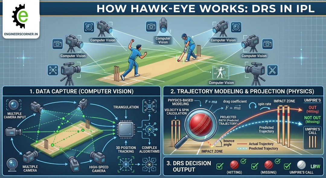
Step 4: Ball Physics – Modeling the Trajectory
Once the system knows the ball’s 3D position across hundreds of time steps, it fits a physical trajectory model to those positions. A cricket ball does not travel in a straight line. Several forces act on it at once.
Gravity
The ball drops at 9.8 meters per second squared, always. This is the baseline of the trajectory model.
Air Drag
At 130 to 150 km/h, air resistance is significant. The drag force on the ball is proportional to the square of its velocity. The system factors in air density, ball diameter, and an estimated drag coefficient. Faster balls drop differently from slower ones.
The Magnus Effect
This is where it gets genuinely interesting. When a ball spins as it moves through air, it creates an unequal pressure distribution on its two sides due to Bernoulli’s principle. The side of the ball where the spin is moving with the airflow experiences lower pressure. The side where spin moves against the airflow has higher pressure. This pressure difference pushes the ball sideways or downward depending on the spin axis.
This is why a leg-spin delivery curves away from a right-handed batsman. The ball is spinning on a specific axis, and the Magnus force acts perpendicular to both the velocity and the spin axis. Hawk-Eye’s cameras can detect the seam position across frames, which tells the system the spin axis and the approximate rotations per minute, which it feeds into the Magnus force calculation.
Seam Movement
New ball seam movement is a turbulent aerodynamics problem. The raised seam creates asymmetric boundary layer separation on the two sides of the ball, generating lateral force. This is harder to model precisely, which is part of why no-ball predictions on seaming deliveries are less confident.
Pitch Bounce
When the ball pitches, it loses some velocity and changes direction. The system uses the observed bounce angle combined with pre-match pitch condition data (where the pitch is grassy, damp, or hard) to model this. The important limitation here: the pitch data is recorded at the start of the match and does not update during play. If dew forms in the evening or the surface breaks down by the 15th over, Hawk-Eye’s bounce model does not reflect that change. This is a genuine engineering limitation, not a flaw in the tracking itself.
Step 5: The LBW Prediction – Where Observation Becomes Extrapolation
Everything up to this point is tracking what the ball actually did. The LBW prediction is different. When the ball hits the batsman’s pad, tracking stops. From that moment, the system has to predict what the ball would have done if the batsman was not there.
This extrapolation uses the last known velocity vector, spin, Magnus force, gravity, and remaining distance to the stumps. It calculates a predicted path and answers three questions:
- Did the ball pitch outside leg stump? If yes, the decision is not out regardless of where it was heading.
- Did the ball hit the batsman in line with the stumps? If the impact was outside the line of off stump, the decision depends on whether the batsman was playing a shot.
- Would the ball have hit the stumps?
For question 3, the system outputs a probability, not a certainty. The ball is predicted to hit a certain part of the stump with some confidence. This directly leads to the concept most fans misunderstand: Umpire’s Call.
Why Umpire’s Call Exists – And Why It Makes Engineering Sense
Hawk-Eye’s accuracy is 2.6 mm. But that figure applies to the tracking phase. The prediction phase, which extends the trajectory beyond the pad, carries additional uncertainty that grows with distance. The further the stumps are from the pad, the wider the confidence interval on where the ball would have ended up.
The ICC defined a zone around the edge of the stumps. If the ball is predicted to hit the stumps but the predicted path passes through that boundary zone, the system does not have enough confidence to overturn the on-field decision. So it defers to the umpire. That is Umpire’s Call.
Think of it this way: in statistics, you would never report a result without its error bars. You would say “the ball is predicted to hit the top of off stump, plus or minus 5 mm.” When the error bar overlaps with the edge of the stump, you cannot confidently say it would have hit. Umpire’s Call is cricket’s implementation of a confidence interval.
This is genuinely good engineering. A system that reports binary yes/no answers when the underlying data is uncertain would be less trustworthy, not more. The controversy around Umpire’s Call usually comes from fans who want certainty that the technology simply cannot provide.
IPL 2025: Hawk-Eye Goes Beyond DRS
IPL 2025 introduced something new that shows how far ball-tracking has come.
Previously, whether a wide was called for a head-high delivery was entirely the umpire’s judgment. Different umpires had different thresholds. From IPL 2025, this judgment has been removed from the equation completely.
The Hawk-Eye ball-tracking system now measures the exact height of the ball as it passes the batter at the popping crease. This height is matched against the batter’s pre-recorded head height when standing upright, stored in a database for each player. If the ball passes above that recorded head height, it is automatically called a wide, with no human subjectivity involved.
The same approach was already applied in IPL 2025 for over-the-waist no-balls. IPL 2026 extended it to wides on the off side and head-high deliveries.
This is a meaningful shift. Hawk-Eye is no longer just a review tool. It is becoming a real-time match officiating system, with automated decisions running continuously during live play. That is a completely different engineering problem from post-delivery review, because the system now needs to output a reliable decision within the time the ball takes to travel from the bowler to the batsman.
Limitations of Hawk-Eye: Because No System Is Perfect
Any article that only talks about how good a technology is without covering its limits is not being straight with you. Hawk-Eye has real constraints.
Pitch Condition Does Not Update
As mentioned above, the pitch data is fixed at match start. A pitch that dries out, gets wet, or breaks down during play will behave differently from what the model expects.
The Prediction Zone Has Real Uncertainty
The further the pad impact is from the stumps, the less reliable the LBW prediction. The system is well calibrated for impacts close to the popping crease, but accuracy decreases with distance.
It Reports the Most Likely Path, Not the Certain Path
The official description of Hawk-Eye is that it shows the ball’s “most statistically likely path.” That wording is precise and honest. It is a probability model, not a ground truth replay of what would have happened.
Cost Limits Deployment
The hardware and calibration requirements are expensive. This is why Hawk-Eye DRS is standard in Test cricket and IPL but not in every domestic T20 league around the world.
The Ashes 2007 Example
In the 2007 Wimbledon Championships, a shot that appeared out was called in by Hawk-Eye by 1 mm, a distance smaller than the system’s own advertised mean error at the time of 3.6 mm. This case is often cited as an example of reporting a binary decision when the data does not support that level of precision. Since then, margins of error and Umpire’s Call zones have been more carefully defined.
What Engineering Roles Connect to This Technology
This section is for students who want to know where this leads career-wise.
Computer Vision Engineer
The ball detection and tracking pipeline described above is exactly what a computer vision engineer builds. Skills needed: Python, OpenCV, deep learning for object detection, multi-camera geometry. Companies in sports tech, automotive (ADAS), and surveillance all hire for this profile.
Sports Data Analyst
Hawk-Eye generates enormous amounts of structured data: ball speed, trajectory coordinates, pitch maps, wagon wheels, bounce locations. IPL franchises and broadcasters hire data analysts to work with this output. SQL, Python, and Tableau are the starting points.
Embedded Systems Engineer
The Zings LED stumps used in IPL are a separate but related product. They use accelerometers and microcontrollers to detect bail dislodgement and trigger LED lights in under a millisecond. That is embedded systems engineering applied directly to cricket.
Physics Simulation Developer
Game studios, sports science companies, and training simulators hire engineers who can model ball physics accurately. Understanding drag, Magnus force, and coefficient of restitution is directly applicable.
The next time a DRS review happens in an IPL match and the 3D graphic appears on screen, you now know what is running behind it. Six monochrome cameras shooting at 120 frames per second. Multi-view triangulation accurate to 2.6 mm. A physics model accounting for gravity, air drag, spin, and seam. A trajectory extrapolation that answers three yes/no questions with an honest error bar attached.
The whole thing runs in roughly two seconds. That is not magic. That is engineering.
Frequently Asked Questions About Hawk-Eye
How many cameras does Hawk-Eye use in cricket? Hawk-Eye uses six high-speed cameras placed on the stadium roof, spaced 60 degrees apart from each other. The spacing is intentional, it maximizes geometric diversity for triangulation, which is what produces the system’s claimed accuracy of 2.6 mm.
How accurate is Hawk-Eye in cricket? Hawk-Eye is advertised to be accurate to within 2.6 mm for ball tracking. However, the LBW prediction phase, which extends the trajectory beyond the pad impact, carries additional uncertainty. This is why the Umpire’s Call zone exists, to account for cases where the predicted path falls within the margin of error.
What is Umpire’s Call in DRS? Umpire’s Call is triggered when Hawk-Eye predicts the ball would have hit the stumps, but the predicted path passes through the boundary zone of the stumps rather than clearly through the middle. In these cases, the system does not have sufficient confidence to overturn the on-field umpire’s decision, so the original call stands. It is essentially a confidence interval applied to match officiating.
How does Hawk-Eye predict an LBW decision? After the ball hits the batsman’s pad, Hawk-Eye has observed its trajectory up to that point. It then extrapolates the trajectory mathematically from the point of pad impact to the stumps, using the ball’s velocity, spin axis, Magnus force, and gravity. The system answers three questions: did the ball pitch outside leg stump, did it hit the pad in line with the stumps, and would it have gone on to hit the stumps.
What is the frame rate of Hawk-Eye cameras? The JAI monochrome cameras used in Hawk-Eye operate at around 120 frames per second, significantly faster than standard broadcast cameras. This high frame rate is necessary to capture a cricket ball moving at 130 to 150 km/h with enough positional data points for accurate triangulation and trajectory fitting.
Who owns Hawk-Eye technology? Hawk-Eye Innovations is owned by Sony. The system was originally developed by Dr. Paul Hawkins and David Sherry at Roke Manor Research in the United Kingdom, with the first cricket application in 2001 during the Ashes series.
What is new in Hawk-Eye for IPL 2025? IPL 2025 extended Hawk-Eye’s automated decision-making to head-high wides and off-side wides. The system now measures the ball’s exact height as it passes the batter and compares it against that player’s pre-recorded head height. If the ball is above the recorded head height, it is automatically declared a wide without any umpire judgment involved.


")


